UNIT 19
OPTICS
(from DOING
Physics: Image Formation by Lenses, Dewey I. Dykstra, Jr. and Wm. S.
(Willy) Smith,
Objectives
· To understand how we see objects
· To understand Snell’s law
· To understand the concept of
refraction
· To understand the concept of total
internal reflection
· To understand the effect of lenses and
mirrors on light
· To be able to use the thin lens
equation to solve problems
· To understand the concept of focal
point
· To understand the concepts of real
image and virtual image
· To understand the concept of
magnification
· To understand and be able to use ray
diagrams
· To understand the differences between
different types of lenses
· To understand the law of reflection
· To understand the differences between
different types of mirrors
· To understand multi-lens systems
· To use the concepts of optics to
understand how the eye, telescope, and microscope work
Equipment:
1 object
1 flashlight
1 self-luminous object
1.1
a. Place an object on a table. Describe why you can see the object. Explain.
b. Turn off all the lights. Can you see the object? Explain.
c. What allows you to see objects? Explain.
d. Place a flashlight (turned on) and a self-luminous object on a table. Can you see the light from the flashlight? The self-luminous object? Can you see the light from the flashlight from all directions? What allows you to see the light from the flashlight and the self-luminous object? Explain.
e. Turn off all the lights. Place a flashlight (turned on) and a self-luminous object on a table. Can you see the light from the flashlight? The self-luminous object? Can you see the light from the flashlight from all directions? What allows you to see the light from the flashlight and the self-luminous object? Explain.
Discuss your ideas with an instructor.
1.2
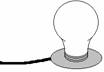
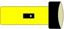
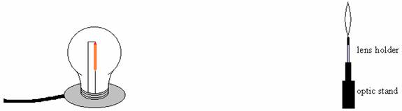
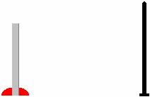
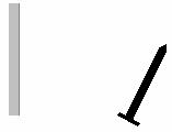
a. Consider how you might represent light coming from a light bulb (turned
on) and a flashlight pictured below. Sketch how you would represent the light
coming from the bulb and the flashlight in the diagram below. Describe what
aspects of the light your diagram is attempting to represent.
b. Could you consider light coming from a light bulb (not turned on) and a
tennis ball? If so, sketch how you would represent the light coming from the
bulb and the tennis ball pictured below.
Describe what aspects of the light your diagram is attempting to
represent.
![]()
Equipment:
1 30cm lens
1 lens holder
1 lamp
1 40W appliance bulb
1 screen holder
1 screen
2 optic stands
1 index card
2.1
a. Start with the lamp approximately 1.2m away from the screen. Place the lens in between the lamp and the screen, so that a clear image of the filament appears on the screen. Remove the lens. Can you create a clear image of the filament on the screen without a lens? Write down ideas that might explain your observations.
b. Place the lens in between the lamp and the screen, so that a clear image of the filament appears on the screen. Move the screen toward and away from the lens. What happens to the image of the filament on the screen? Write down ideas that might explain your observations.
c. With the lens in between the lamp and the screen, so that a clear image of the filament appears on the screen, compare the image to the object. Is the image upside down? Rightside up? Write down ideas that might explain your observations.
Equipment:
1 30cm lens
1 lens holder
1 lamp
1 40W appliance bulb
1 screen holder
1 screen
2 optic stands
1 index card with pinhole
2.2
a. With the lamp approximately 1.2m away from the screen. Place an index card with a pinhole in between the lamp and the screen. Is there anywhere that you can place the index card with a pinhole so that a clear image of the filament appears on the screen? Is there more that one place that you can place the index card with a pinhole so that a clear image of the filament appears on the screen? Write down ideas that might explain your observations.
b. With the index card with a pinhole in between the lamp and the screen, so that a clear image of the filament appears on the screen, compare the image to the object. Is the image upside down? Rightside up? Write down ideas that might explain your observations.
Equipment:
1 30cm lens
1 lens holder
1 lamp
1 40W appliance bulb
1 screen holder
1 screen
2 optic stands
1 index card
3.1
a. With the lens back in place and a clear image of the filament on the screen what would happen if you covered half the lens with an index card? What would happen if you covered the right half? The left half? The top? The Bottom? Explain. What if you covered more than half of the lens? What if you covered all but a small hole? Write down ideas that might explain your observations.
b. Test your predictions in part a. Write down ideas that might explain your observations.
Equipment:
1 30cm lens
1 lens holder
1 lamp
1 40W appliance bulb
1 screen holder
1 screen
2 optic stands
1 index card with pinhole
4.1
a. If the lens is placed so that a clear image of the filament appears on the screen, and the screen is removed, is there any position from which you can still see the image? Write down ideas that might explain your observations.
Check your observations with an instructor.
b. With the lamp fixed in place, move the lens toward and away from the screen. Is there more than one place that you can place the lens so that a clear image of the filament appears that you can see either with or without a screen? Write down ideas that might explain your observations.
Equipment:
1 light box
1 rectangular box
1 solid, rectangular acrylic box
water
1 Sheet 1 at the end of the unit
1 protracter
5.1
a. Summarize your ideas about how light is effected by a lens.
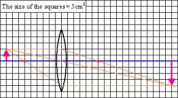
b. Consider the picture below.
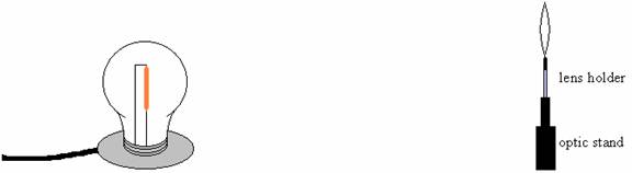
Does all the light from the filament go through the lens? Is there an image of the filament produced somewhere? Sketch a representation of the light leaving the filament. Explain.
Consider only the top point of the filament (indicated in red).
Sketch a representation of the light leaving the top point of the filament. Does all the light from the top point of the filament go through the lens? Is there an image of the top point of the filament produced somewhere? Explain.
The top point of the filament is like a point source of light. Light leaves the top point of the filament in all directions. One might sketch a representation of the light leaving a point source as in the picture below.
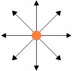
The arrows represent the direction of travel of light. We will call the arrows light rays. If a lens were placed near a point source, not all the light from the point source would go through lens and the light rays that do would enter the lens at different angles.
It is useful to consider a source of light with all of the light rays leaving the source in the same direction. A light box is a source of light with all of the rays leaving the box in (approximately) the same direction.
In order to develop a detailed model of light traveling through a lens, we will first study a simple model. We will use a light box to study the path of light when it travels from one medium to another.
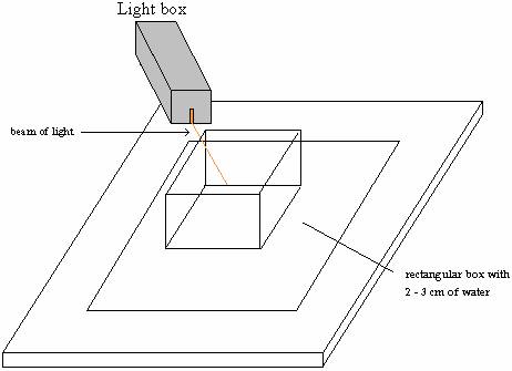
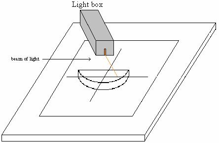
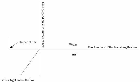
c. Print out Sheet 1 at the end of the unit. Place Sheet 1 on the table, as in the picture below and place the clear, plastic rectangular box half filled with water on the sheet, as indicated. Place the light box so the light beam is at 350 from the line perpendicular to the front of the box.
(adapted from DOING
Physics: Image Formation by Lenses, Dewey
I. Dykstra, Jr. and Wm. S. (Willy) Smith,
d. Trace the path of light entering and exiting the box. Observe the path of light through the water. Then remove the box and draw path of light through the water. Measure the angle that the path light through the water makes with the line perpendicular to the front surface of the box.
e. Replace the rectangular box with a solid, rectangular box made of acrylic and repeat part d. What is different between part d and part e?
f. What happens to the direction of the light when it goes from air to water? What happens to the direction of the light when it goes from water to air? What happens to the direction of the light when it goes from one medium to another?
g. For the rectangular box with water in it, repeat part d with the light entering the water at different angles. Use the angles in the table below. The angle the light makes with the line perpendicular with the front surface box before entering the water we will call qi. The angle the light makes with the line perpendicular with the front surface box after entering the water we will call qr. Fill out the table below.
|
Angle before entering water (qi) |
Angle after entering water (qr) |
sin qi |
sin qr |
sin qi/sin qr |
|
0 |
|
|
|
|
|
10 |
|
|
|
|
|
30 |
|
|
|
|
|
50 |
|
|
|
|
|
70 |
|
|
|
|
h. Repeat part g for the acrylic box.
|
Angle before entering acrylic (qi) |
Angle after entering acrylic (qr) |
sin qi |
sin qr |
sin qi/sin qr |
|
0 |
|
|
|
|
|
10 |
|
|
|
|
|
30 |
|
|
|
|
|
50 |
|
|
|
|
|
70 |
|
|
|
|
When the direction of light changes when the light passes from one medium to another, the "bending" of light is called refraction. If light travels from air into another medium, the ratio of the sin of the angle before entering the medium to the sin of the angle after entering the medium is called the index of refraction of that medium.
More generally, the speed of light is different in different materials. The index of refraction of a material is defined as the ratio of the speed of light in a vacuum to the speed of light in the material:
n = the speed of light in a vacuum / the speed of light in the material
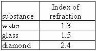
The speed of light in air, is approximately equal to the speed of light in a vacuum, so the index of refraction of air, nair, is approximately equal to one, and we will use nair = 1. The index of refraction of some materials is listed in the table below.
When light passes from one material to another, the ratio ![]() , is equal to the inverse ratio of their indices of
refraction:
, is equal to the inverse ratio of their indices of
refraction:
![]()
where ![]() is the angle
of the incident light measured from a line perpendicular to the
boundary and
is the angle
of the incident light measured from a line perpendicular to the
boundary and ![]() is the angle of
the refracted light measured from a line perpendicular to the boundary, ni
is the index of refraction of the material in which the incident light is
traveling and nr is the index of refraction of the material in which
the refracted light is traveling. This is called Snell's Law.
is the angle of
the refracted light measured from a line perpendicular to the boundary, ni
is the index of refraction of the material in which the incident light is
traveling and nr is the index of refraction of the material in which
the refracted light is traveling. This is called Snell's Law.
5.2
Equipment:
1 light pipe
1 fiber optics cable
1 laser
a. Consider light traveling from a medium of higher
index of refraction into a medium of lower index of refraction. Consider, for
example, light traveling from glass into air. If the angle of incidence, ![]() , is 53°, what is the angle of refraction,
, is 53°, what is the angle of refraction, ![]() ?
?
b. What happens to light that is traveling from glass into air at an angle of 53°? What is your idea? Explain.
c. Using a laser, observe how light travels through a light pipe when the light is incident on the side of the pipe at small angles and at large angles. For each case, is almost all of the light that enters the pipe leaving the pipe? Is light refracted at the sides of the pipe?
d. When light travels from a medium of higher index of refraction into a medium of lower index of refraction, there are angles at which all of the light is reflected, no light passes into the other medium. This is called total internal reflection. How could you mathematically determine the minimum angle at which all of the light is reflected? Explain.
When light travels from a medium of higher index of
refraction into a medium of lower index of refraction, there is a minimum angle
at which all of the light is reflected. This is called the critical angle, ![]() . The critical angle is the incident angle at which the
refracted angle is 90°.
. The critical angle is the incident angle at which the
refracted angle is 90°.
![]()
e. A fiber optic cable works like a light pipe. Fiber optic cables are used to view objects in inaccessible locations. Physicians use fiber optic cables to examine internal organs of the body, using a device called an endoscope. In an endoscope, one bundle of optical fibers carries light into the body, and another bundle carries the reflected light back to the eye of the observer. It can also be used to perform surgery. Fiber optic cables are also used in telecommunications because they can carry a higher volume of information than copper wires. Observe light traveling through a fiber optics cable.
Equipment:
1 sheet of white paper
1 light box
1 solid, semi-circular piece of acrylic
6.1
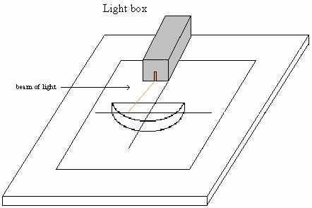
a. Observe a ray of light going through a semi-circular piece of acrylic, as in the picture below. Is the path of light consistent with Snell's law? Carry out the calculations.
b. Observe a ray of light going through a semi-circular piece of acrylic at a different angle.
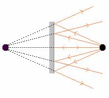
c. Suppose a point source of light were placed near the semi-circular piece of acrylic, as in the picture below. Sketch the path of four rays of light from the point source.
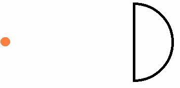
Is there anywhere where the rays of light from the point source come back together? If you were to place a screen behind the piece of acrylic, what would appear on the screen, as you moved the screen back?
d. The light bulb in the light box is approximately a point source. Use it to test your predictions in part c.
e. Suppose you had four point sources of light as in the diagram below.
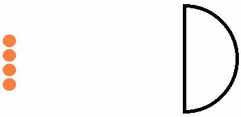
Is there anywhere where the rays of light reform into four point sources? If you were to place a screen behind the piece of acrylic, what would appear on the screen, as you moved the screen back? Would you see an image of the four point sources on the screen at any point? Explain.
A piece of material shaped in such a way, that light from an object or light source passing through the material forms an image is called a lens. A lens may have one side curved, like the piece of acrylic, or it may have both sides curved.
f. A filament can be considered to be a series of point sources. In parts 2.1, 4.1.a, and b and 5.1.a you observed a filament through a lens. Discuss how your observations are consistent with the experiments in parts a through e in this section.
Equipment:
1 light ray box
1 convex acrylic lens
1 concave acrylic lens
7.1
a. Use the ray box to direct five approximately parallel rays through a lens as in each of the pictures A and B below.
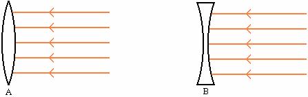
Lenses shaped as in diagram A are called convex or converging lenses and those shaped as in diagram B are called concave or diverging lenses.
When parallel rays enter a convex lens, the place where the rays cross is called the focal point of the lens. The distance from the center of the lens to the focal point is called the focal length of the lens.
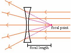
Parallel rays passing through a concave lens all appear to emanate from the same point. The point from which they appear to emanate is called focal point of the lens. The distance from the center of the lens to the focal point is called the focal length of the lens.
b. Consider an object in the shape of an arrow placed 45cm from a 30cm focal length lens, as in the picture below.
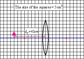
There are many rays of light from the top of the arrow that pass through the lens. It is sufficient to draw only two of those rays to find the location of the top of the image of the arrow. We could determine the path of the rays from the law of refraction, but we know that a ray coming in parallel to the axis of the lens must go through the focal point and, by symmetry, a ray through the focal point, would leave parallel. These two rays can determine the top of the image of the arrow. If the bottom of the arrow is on the axis of the lens, the bottom of the image of the arrow, must lie on that axis. The image of the arrow, must be as in the diagram below.
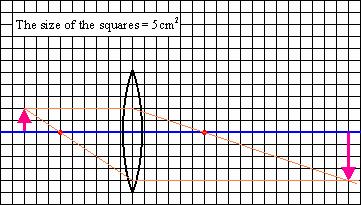
From the diagram, we could measure the distance of the image from the lens (called the image distance). The image distance is 90cm.
The magnification is
the ratio of the image height (![]() ) to the object height (
) to the object height (![]() ). It is common to define the magnification to be positive
when the image is upright and negative when the image is inverted. If the image
is inverted then
). It is common to define the magnification to be positive
when the image is upright and negative when the image is inverted. If the image
is inverted then ![]() is considered to be
negative.
is considered to be
negative.
![]()
A line drawn from the tip of the arrow to the tip of the image would pass through the center of the lens.
From geometry, the ratio of the object height to the image height is
![]()
It can also be shown
(and will not be shown here) that for a thin lens the focal length (![]() ), object distance (
), object distance (![]() ) and image distance (
) and image distance (![]() ) are related by the following equation
) are related by the following equation
![]()
with the following set of rules:
1. ![]() is positive if the
object is to the left of the lens and negative if it is to the right of the lens.
is positive if the
object is to the left of the lens and negative if it is to the right of the lens.
2. ![]() is positive if the
image is to the right of the lens and negative if it is to the left of the
lens.
is positive if the
image is to the right of the lens and negative if it is to the left of the
lens.
3. The focal length, ![]() , is positive for a convex (converging) lens and negative for
a concave (diverging) lens.
, is positive for a convex (converging) lens and negative for
a concave (diverging) lens.
The magnification is then defined as
![]()
The formula ![]() is called the thin
lens equation.
is called the thin
lens equation.
Equipment:
lenses
1 lens holder
1 lamp
1 40W appliance bulb
1 screen holder
1 screen
2 optic stands
1 mirror
1 nail
8.1
a. It is possible to see an image through a lens that cannot be seen on a screen. If the image cannot be seen on a screen, there is no light where the image appears to be. This is called a virtual image. Try to demonstrate this.
Discuss with an instructor.
This is more easily seen by studying mirrors.
b. Set up a mirror and a nail as in the diagram below.
Where is the image of the nail? Mark the image of the nail. How can you tell where the image is? Explain.
Discuss with an instructor.
c. Is there light coming from the image of the nail? Explain.
Equipment:
1 Sheet 2 at the end of the unit
1 mirror
1 lightbox
1 protractor
9.1
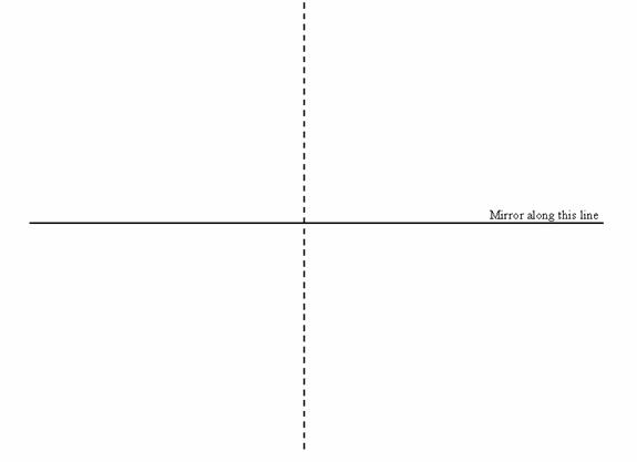
a. Place the mirror on the solid line on Sheet 2.Use the light ray box with a single slit to determine the path of the light before it strikes the mirror and after reflection from the mirror.
Measure the angle of
incidence, ![]() (the angle the
incoming light ray makes with the line perpendicular to the surface of the mirror),
and the angle of reflection,
(the angle the
incoming light ray makes with the line perpendicular to the surface of the mirror),
and the angle of reflection, ![]() (the angle the
reflected light ray makes with the line perpendicular to the surface of the
mirror), for the angles in the table below.
(the angle the
reflected light ray makes with the line perpendicular to the surface of the
mirror), for the angles in the table below.
|
Angle of Incidence (qi) |
Angle of reflection (qr) |
|
0 |
|
|
20 |
|
|
40 |
|
|
60 |
|
|
80 |
|
b. How is the angle of incidence related to the angle of reflection for a mirror?
For a mirror, the angle of incidence is equal to the angle of reflection:
![]()
This is called the law of reflection.
Equipment:
1 mirror
1 nail
1 protractor
10.1
a. Consider a nail lying near a mirror, as in the picture below. (The picture shows a top view of the nail and the mirror.) Use the law of reflection to determine the direction of the reflected rays from the nail for 5 or 6 rays from the nail.
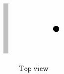
When the reflected rays enter your eye, where do they appear to be coming from?
Why do you see an image of the nail at a point behind the mirror?
Is there light at the point of the image? Is there light coming from the image?
When an image can be seen, but no light is emanating from the image, it is called a virtual image.
It is useful to draw dotted lines backwards to the point of emanation of the rays, as in the picture below.
How does the object distance compare to the image distance for the nail in the picture above?
b. Consider a nail lying on its side as in the picture below. (The top view of the nail is shown.)
Can you see the whole image of the nail from any viewing angle?
What determines whether or not you can see the whole nail?
c. Draw a ray diagram for rays at the tip and the base of nail to help explain the part of the nail you see at different angles.
Discuss your reasoning with an instructor.
Equipment:
1 30cm lens
1 20cm lens
2 lens holder
2 optic stands
1 document with fine print
11.1
a. Observe fine print through a 30cm lens. Place the lens at a distance at which the fine print is magnified. See if you can magnify the print even more, using a second lens, in addition to the 30cm lens.
When more than one thin lens is used in an optical system, the image of the first lens is the object of the second lens and the thin lens formula must be applied successively for each lens.
For your optical setup, determine the
· image distance of first lens
· object distance of the second lens
· image distance of the second lens
· the magnification of each lens
· the total magnification of the lens system
Discuss with an instructor.
The total magnification of a multiple lens system is the product of the magnification of each lens.
An optical setup of more than one lens is the principle behind microscopes and telescopes.
SUMMARY
You should understand how we see objects. You should understand the
concept of refraction, the concept of total internal reflection and be able to
use Snell's Law.
You should understand the effect of lenses and mirrors on light. You
should understand the concept of the focal point. You should understand the
concept of magnification. You should be able to use ray diagrams. You should be
able to use the thin lens equation to solve problems. You should understand the
differences between different types of lenses. You should understand the
concepts of real image and virtual image. You should understand multi-lens
systems. You should understand the law of reflection. You should understand
differences between different types of mirrors. You should be able to use the
concepts of optics to understand how the eye, telescope, and microscope work.
Sheet 1
Sheet 2