UNIT 6
DIRECT CURRENT CIRCUITS: INTRODUCTION
(from Lillian C. McDermott and the Physics Education Group,
Physics by Inquiry Volume II, John Wiley and Sons, NY, 1996)
Objectives
· to understand the concept of a closed
circuit
· to understand how conductors and
insulators behave in a circuit
· to be able to draw circuit diagrams
for physical circuits
· to be able to set up physical circuits from circuit diagrams
Equipment:
1 battery
1 light bulb
1 flashlight
1 10cm piece of wire (stripped at both ends)
1.1
a. Obtain one battery, one light bulb and one wire. Connect these in as many ways as you can. Find four arrangements that light the bulb and four arrangements that do not light the bulb. Sketch all of the arrangements.
b. State what requirements must be met in order for the bulb to light.
c. Examine a flashlight. What requirements must be met in order for the bulb to light?
d. The term closed circuit is used for arrangements that light the bulb. Explain why this is a reasonable terminology by discussing how the elements in the circuit must be connected in order to light the bulb.
Equipment:
1 battery
1 light bulb
1 large bulb with glass removed
2-3 10cm piece of wire (stripped at both ends)
different materials (include copper, paper, aluminum, plastic, nichrome wire, rubber, glass and pencil lead)
2.1
a. Obtain a battery, bulb, two wires and objects made out of different materials (be sure to include copper, paper, aluminum, plastic, nichrome wire, rubber, glass and pencil lead). Insert the objects into the circuit. Observe what happens to the bulb when each of the objects is inserted. Classify the objects according to their effect on the bulb.
Objects that allow the bulb to glow brightly are called conductors. Objects that make the bulb to go out are called insulators. Some objects lie between the two categories.
b. Obtain a large light bulb with the glass removed. Use a test circuit (battery, small bulb and wire(s)) to determine where the two wires coming up from inside the base of the bulb originate. Which parts of the bulb are conductors and which parts of the bulb are insulators?
Equipment:
1 battery
1 battery holder
1 switch
1 light bulb
1 light socket
4-5 alligator clip wires
3.1 Obtain a battery, bulb, wires with alligator clips, battery holder, socket, and a switch.
a. Using a battery, a battery holder, a bulb, a socket, and two wires, set up a circuit that lights the bulb. Trace the path of the conductors around the circuit.
b. Connect the battery (in a holder), bulb (in a socket) and switch in such a way that closing the switch lights the bulb.
This is called an open circuit when the switch is open. Discuss why the bulb doesn’t light when the switch is open.
Equipment:
None
4.1 Circuit diagrams let us represent a circuit on paper by using common symbols for the batteries, bulbs, switches and other circuit elements. We will use the following symbols for circuit elements:
![]()
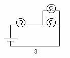
Circuit diagrams show electrical connections and not physical layout. The two circuits, (1) and (2), shown below, are represented by the same circuit diagram (3).

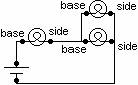
The statement that circuit diagrams show electrical connections means that they show which end of each element is connected to the ends of other elements. More than one other element may be connected to each end of an element, but connections can only be made to an end of an element. It may be useful to label the ends of each element. For example, a bulb could be labeled
![]()
and the above diagram could be labeled
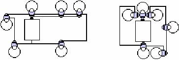
a. Consider the following physical circuits. Draw circuit diagrams for each of the circuits pictured.
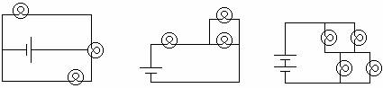
b. Consider the following student circuit diagrams. Set up the circuits represented. If you cannot set up the circuit represented by a diagram, explain what about the diagram is incorrectly drawn.
c. The instructor will set up circuits at your table. Draw a circuit diagram for each circuit.
As you saw in 4.1, it is possible to connect batteries and bulbs in different ways. Whether or not the bulbs in a circuit will light, and the magnitude of their brightness, depends on how they are connected. We would like to be able to predict the brightness of bulbs in a circuit, if we know how they are connected. In order to do this, we have to develop a model, based on our experimentation, which will allow us to predict the brightness of bulbs in many different circuits. We will do this in the next sections.
SUMMARY
You should be able to understand the concept of a closed circuit. You should understand how conductors and insulators behave in a circuit. You should be able to draw circuit diagrams for physical circuits and be able to set up physical circuits from circuit diagrams.